

A diode is an electrical device allowing current to move through it in one direction with far greater ease than in the other. The most common kind of diode in modern circuit design is the semiconductor diode, although other diode technologies exist. Semiconductor diodes are symbolized in schematic diagrams such as Figure below. The term “diode” is customarily reserved for small signal devices, I ≤ 1 A. The term rectifier is used for power devices, I > 1 A
In electronics, a diode is a two-terminal electronic component that conducts primarily in one direction (asymmetric conductance); it has low (ideally zero) resistance to the flow of current in one direction, and high (ideally infinite) resistance in the other. A semiconductor diode, the most common type today, is a crystalline piece of semiconductor material with a p–n junction connected to two electrical terminals..

Semiconductor diode schematic symbol: Arrows indicate the direction of electron current flow.
Ideal Diodes
The key function of an ideal diode is to control the direction of current-flow. Current passing through a diode can only go in one direction, called the forward direction. Current trying to flow the reverse direction is blocked. They’re like the one-way valve of electronics.
If the voltage across a diode is negative, no current can flow, and the ideal diode looks like an open circuit. In such a situation, the diode is said to be off or reverse biased.
As long as the voltage across the diode isn’t negative, it’ll “turn on” and conduct current. Ideally a diode would act like a short circuit (0V across it) if it was conducting current. When a diode is conducting current it’s forward biased(electronics jargon for “on”).
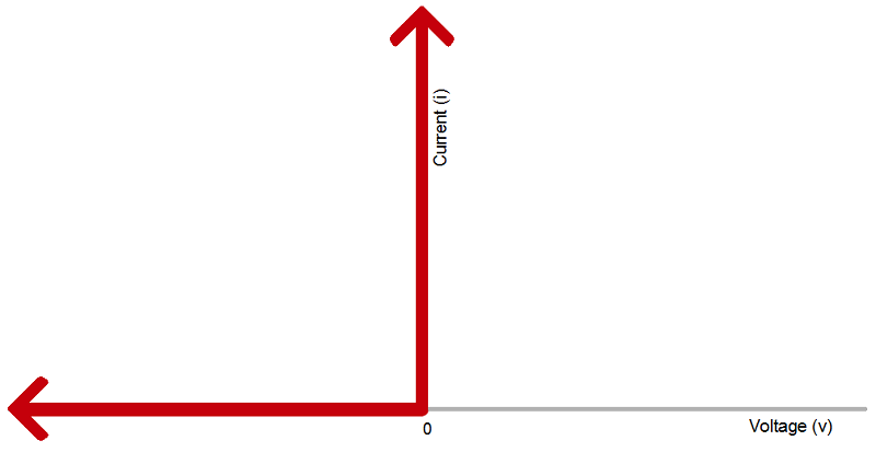
The current-voltage relationship of an ideal diode. Any negative voltage produces zero current – an open circuit. As long as the voltage is non-negative the diode looks like a short circuit.
| Ideal Diode Characteristics | ||
| Operation Mode | On (Forward biased) | Off (Reverse biased) |
|---|---|---|
| Current Through | I>0 | I=0 |
| Voltage Across | V=0 | V<0 |
| Diode looks like | Short circuit | Open circuit |
Real Diode Characteristics
Ideally, diodes will block any and all current flowing the reverse direction, or just act like a short-circuit if current flow is forward. Unfortunately, actual diode behavior isn’t quite ideal. Diodes do consume some amount of power when conducting forward current, and they won’t block out all reverse current. Real-world diodes are a bit more complicated, and they all have unique characteristics which define how they actually operate.
Current-Voltage Relationship
The most important diode characteristic is its current-voltage (i-v) relationship. This defines what the current running through a component is, given what voltage is measured across it. Resistors, for example, have a simple, linear i-v relationship…Ohm’s Law. The i-v curve of a diode, though, is entirely non-linear. It looks something like this:
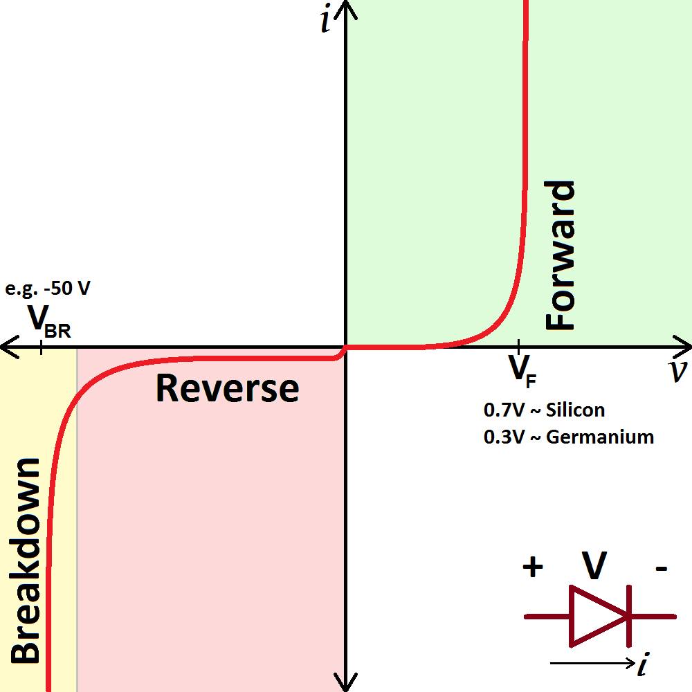
The current-voltage relationship of a diode. In order to exaggerate a few important points on the plot, the scales in both the positive and negative halves are not equal.
Depending on the voltage applied across it, a diode will operate in one of three regions:
- Forward bias: When the voltage across the diode is positive the diode is “on” and current can run through. The voltage should be greater than the forward voltage (VF) in order for the current to be anything significant.
- Reverse bias: This is the “off” mode of the diode, where the voltage is less than VF but greater than -VBR. In this mode current flow is (mostly) blocked, and the diode is off. A very small amount of current (on the order of nA) – called reverse saturation current – is able to flow in reverse through the diode.
- Breakdown: When the voltage applied across the diode is very large and negative, lots of current will be able to flow in the reverse direction, from cathode to anode.
A thin depletion region exists around the region of the P-N junction, preventing current flow. (Figure below (a)) The depletion region is almost devoid of available charge carriers, and acts as an insulator:

The schematic symbol of the diode is shown in Figure above (b) such that the anode (pointing end) corresponds to the P-type semiconductor at (a). The cathode bar, non-pointing end, at (b) corresponds to the N-type material at (a). Also note that the cathode stripe on the physical part (c) corresponds to the cathode on the symbol.
If a reverse-biasing voltage is applied across the P-N junction, this depletion region expands, further resisting any current through it. (Figure below)

Conversely, if a forward-biasing voltage is applied across the P-N junction, the depletion region collapses becoming thinner. The diode becomes less resistive to current through it. In order for a sustained current to go through the diode; though, the depletion region must be fully collapsed by the applied voltage. This takes a certain minimum voltage to accomplish, called the forward voltage as illustrated in Figure below.

For silicon diodes, the typical forward voltage is 0.7 volts, nominal. For germanium diodes, the forward voltage is only 0.3 volts. The chemical constituency of the P-N junction comprising the diode accounts for its nominal forward voltage figure, which is why silicon and germanium diodes have such different forward voltages. Forward voltage drop remains approximately constant for a wide range of diode currents, meaning that diode voltage drop is not like that of a resistor or even a normal (closed) switch. For most simplified circuit analysis, the voltage drop across a conducting diode may be considered constant at the nominal figure and not related to the amount of current.
Actually, forward voltage drop is more complex. An equation describes the exact current through a diode, given the voltage dropped across the junction, the temperature of the junction, and several physical constants. It is commonly known as the diode equation:

The term kT/q describes the voltage produced within the P-N junction due to the action of temperature, and is called the thermal voltage, or Vt of the junction. At room temperature, this is about 26 millivolts. Knowing this, and assuming a “nonideality” coefficient of 1, we may simplify the diode equation and re-write it as such:

0 comments:
Post a Comment