In electronics, a varicap diode, varactor diode, variable capacitance diode, variable reactance diode or tuning diode is a type of diode designed to exploit the voltage-dependent capacitance of a reversed-biased p–n junction.

Varactor diode circuit symbol
A tuning diode, also known as a varactor diode, variable capacitance diode, varicap diode or
variable reactance
diode, is a diode that has a variable capacitance which is a function of the voltage that is
impressed on its terminals. Tuning / varactor diodes are operated reverse-biased, and
therefore no current flows.
However, since the thickness of the depletion zone varies with the applied bias
voltage, the capacitance of the diode can be made to vary. Usually, the capacitance is
inversely proportional to the depletion region thickness and the depletion region thickness
is proportional to the square root of the applied voltage. Therefore, the
capacitance is inversely proportional to the square root of the voltage applied to the diode.
Varactor diode applications
Varactor diodes are widely used within the RF design arena. They provide a method of varying he capacitance within a circuit by the application of a control voltage. This gives them an almost unique capability and as a result varactor diodes are widely used within the RF industry.
Although varactor diodes can be used within many types of circuit, they find applications within two main areas:
- Voltage controlled oscillators, VCOs: Voltage controlled oscillators are used for a variety of applications. One major area is for the oscillator within a phase locked loop - this are used in almost all radio, cellular and wireless receivers. A varactor diode is a key component within a VCO.
- RF filters: Using varactor diodes it is possible to tune filters. Tracking filters may be needed in receiver front end circuits where they enable the filters to track the incoming received signal frequency. Again this can be controlled using a control voltage. Typically this might be provided under microprocessor control via a digital to analogue converter.
Varactor diode basics
The varactor diode or varicap diode consists of a standard PN junction, although it is obviously optimised for its function as a variable capacitor. In fact ordinary PN junction diodes can be used as varactor diodes, even if their performance is not to the same standard as specially manufactured varactors.
The basis of operation of the varactor diode is quite simple. The diode is operated under reverse bias conditions and this gives rise to three regions. At either end of the diode are the P and N regions where current can be conducted. However around the junction is the depletion region where no current carriers are available. As a result, current can be carried in the P and N regions, but the depletion region is an insulator.
This is exactly the same construction as a capacitor. It has conductive plates separated by an insulating dielectric.
The capacitance of a capacitor is dependent on a number of factors including the plate area, the dielectric constant of the insulator between the plates and the distance between the two plates. In the case of the varactor diode, it is possible to increase and decrease the width of the depletion region by changing the level of the reverse bias. This has the effect of changing the distance between the plates of the capacitor.
Varactor diode symbol
As the primary function of a varactor diode is as a variable capacitor, its circuit symbol represents this. Sometimes they may be shown as ordinary diodes, whereas more usually the varactor diode circuit symbol shows the bar as a capacitor, i.e. two lines.

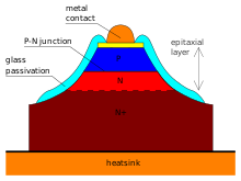
Internal structure of a varicap
| |
| Type | Passive |
|---|---|
| Pin configuration | anode and cathode |
| Electronic symbol | |
 | |
Varactor diodes are always operated under reverse bias conditions, and in this way there is no conduction. They are effectively voltage controlled capacitors, and indeed they are sometimes called varicap diodes, although the term varactor is more widely used these days.
Varactor diodes, or as they are sometimes called, varicap diodes are a particularly useful form of semiconductor diode. Finding uses in many applications where electronically controlled tuning of resonant circuits is required, for items such as oscillators and filters, varactor diodes are an essential component within the portfolio of the electronics design engineer. However to be able to use varactor diodes to their best advantage it is necessary to understand features of varactor diodes including the capacitance ratio, Q, gamma, reverse voltage and the like. If used correctly, varactor diodes provide very reliable service particularly as they are a solid state device and have no mechanical or moving elements as in their mechanical variable capacitor counterparts.
Operation
Varactors are operated in a reverse-biased state. No current flows, but since the thickness of the depletion zone varies with the applied bias voltage, the capacitance of the diode can be made to vary. Generally, the depletion region thickness is proportional to the square rootof the applied voltage; capacitance is inversely proportional to the depletion region thickness. Thus, the capacitance is inversely proportional to the square root of applied voltage.
All diodes exhibit this phenomenon to some degree, but varactor diodes are manufactured specifically to exploit this effect and increase the capacitance (and thus the range of variability), whereas most ordinary diode fabrication strives to minimize the capacitance.
The figure shows an example of a cross section of a varactor with the depletion layer formed of a PN junction. This depletion layer can also be made of a MOS or a Schottky diode. This is very important in CMOS and MMIC technology.


0 comments:
Post a Comment